New (2023)
The updated version of the peregrine UAV uses a singular RP2040 chip with the CYW43 network card running FreeRTOS
Master Map
Link to original
Sensors
- Barometric Pressure Sensor
- Accelorometer/Gyroscope
- Magnetometer
- Ultrasonic Sensor (backup is LiDar in case of noise interference)
- Magnetometer not needed for takeoff stage
- GPS not needed for takeoff stage
- Temperature Sensor not required
Barometric Pressure Sensor
Communication Type:
Model :
Accelorometer
Communication Type:
Model:
Ultrasonic Sensor / LIDAR Sensor
Communication Type:
Model:
Peripherals
Technically none of these are NECESSARY although they add extra support for debugging (and they look/sound cool)
- OLED Screen
- Heartbeat LED built-in
- Status LED
- Buzzer
OLED Screen
Communication Type: I2C
Model:
Motion
- Brushless motor x4
- Servo x2
- ESC x4
- Servo x2 not needed for takeoff stage
Brushless Motor
Control Type: PWM
Model: DJI
Servo
Control Type: PWM
Model:
Power
- 2s LIPO
- PCB Power
- 6s LIPO
- Motors / Servos Power
Early PCB Designs
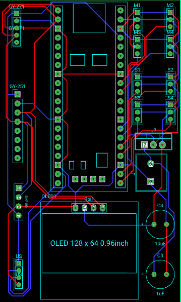
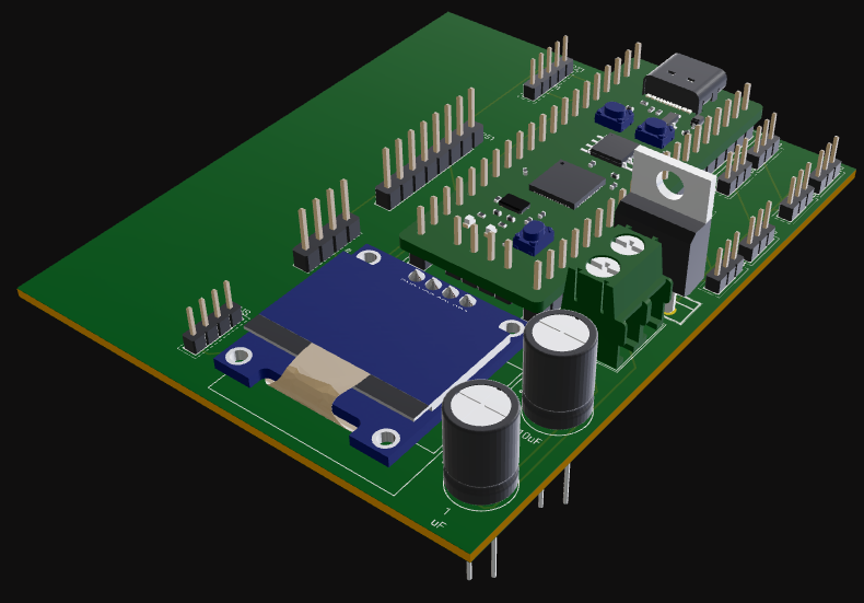
Old
List
Chips
- STM32F4
- ATMEGA164PU
Sensors
- Barometric Pressure
- Accelorometer
- Ultrasonic Distance
- GPS
- Temperature: x1-5
- Theses will use I2C ADC chips (1 can take in 3 analog signals)
- PCB
- Motor 1-4
Communication
- ESP Wifi Module
Error Code / Status
- OLED display
- Buzzer
- LED x10 (STM:4, ATMEGA:5, Passive:1)
- STM32 Master Status: x3 (Connected to STM32)
- green
- yellow
- red
- ATMEGA Master Status: x3 (Connected to ATMEGA)
- PCB power status (Connected to power)
- WiFi Com Status (Connected to ATMEGA)
- STM > ATMEGA Com Status x2 (Connected to ATMEGA & STM32)
- STM32 Master Status: x3 (Connected to STM32)
Data Logging
- Micro SD r/w
Movement
- DJI Inspire 1 motor: x4
- Servo: x4
- TVC vertical
- TCV horizontal
- Left aileron
- Right aileron
- ESC: x4
Power
- 2s LIPO
- PCB Power
- 6s LIPO
- Motor Power
MAP
flowchart LR
subgraph STM32F4
	usart1[USART]
	usart5[USART]
	i2c1[I2C]
	gpio1[GPIO]
	gpio2[GPIO]
	gpio3[GPIO]
	gpio4[GPIO]
	gpio5[GPIO]
	gpio11[GPIO]
end
subgraph ATMEGA164PU
	usart2[USART]
	usart4[USART]
	i2c2[I2C]
	gpio6[GPIO]
	gpio7[GPIO]
	gpio8[GPIO]
	gpio9[GPIO]
	gpio10[GPIO]
end
subgraph ESPWIFI
	usart3[USART]
	wifi1[Wireless Interface]
end
subgraph sensors
	adc1[ADC to I2C]
	adc2[ADC to I2C]
	temp1[Temperature Sensor]
	temp2[Temperature Sensor]
	temp3[Temperature Sensor]
	temp4[Temperature Sensor]
	temp5[Temperature Sensor]
	bar1[Barometric Pressure Sensor]
	acc1[Accelorometer]
	us1[UltraSonic Distance Sensor]
	gps1[GPS]

	temp1 --ANALOG--> adc1
	temp2 --ANALOG--> adc1
	temp3 --ANALOG--> adc1
	temp4 --ANALOG--> adc2
	temp5 --ANALOG--> adc2
end
subgraph status_indicators
	led1[STM32 GREEN]
	led2[STM32 YELLOW]
	led3[STM32 RED]
	led4[ATMEGA GREEN]
	led5[ATMEGA YELLOW]
	led6[ATMEGA RED]
	led7[PCB Power]
	led8[WiFi Communication]
	led9[USART to ATMEGA]
	led10[USART to STM32]
	buz1[BUZZER]
	oled1[OLED Display]
end
subgraph movement
	m1[MOTOR]
	m2[MOTOR]
	m3[MOTOR]
	m4[MOTOR]
	srv1[TVC Vertical Servo]
end
usart1 --USART--> usart2
usart4 --USART--> usart3

i2c1 --I2C--> bar1
i2c1 --I2C--> acc1
i2c1 --I2C--> adc1
i2c1 --I2C--> adc2
usart5 --USART--> gps1
gpio1 --> us1

gpio2 --> led1
gpio3 --> led2
gpio4 --> led3
gpio5 --> led9
gpio6 --> led4
gpio7 --> led5
gpio8 --> led6
gpio9 --> led8
gpio10 --> led10
gpio11 --> buz1
i2c2